|
How-to: Knock Sensor Replacement on a VE30DE (92-94 MaximaSE)
FAQ
Q) What does a knock sensor do?
A) A knock sensor is a specially designed listening device
for car engines. It listens for engine knock, or detonation (pinging).
Detonation can be very bad for an engine and is the result of the fuel/air
mixture exploding too quickly instead of burning evenly and rapidly. This is
due to either bad fuel, ignition timing which is too high, or built up carbon
deposits in the engine (which increases the compression ratio). The sensor is
small and consists of a piezoelectric sensor that listens for knock by detecting
pressure. It is very sensitive and can be considered worthless if dropped.
The vibrational pressure is then converted into a voltage and sent to the ECU
for evaluation.
Q) How do I know if my knock sensor is bad?
A) Symptoms of a bad knock sensor include a sluggish
engine, poor acceleration and poor fuel economy. Knock sensors rarely fail
outright and more often get “soft” over time and cause false signals to be
sent to the ECU, which thinks the engine is knocking when it’s really not.
Thus, the ECU will reduce the ignition timing to the engine. The knock sensor
on the VE30DE is prone to corrosion of the terminals and harness connection.
This is due to the harness weather seal getting brittle and cracking,
allowing moisture to seep into the harness from the rear and corrode the
terminals. This creates a poor connection and faulty voltage readings to the
ECU.
Q) How do I test my knock sensor?
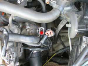
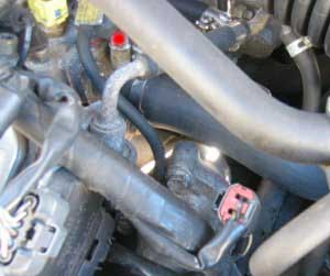
A) The knock sensor voltage can be checked through an electrical
harness located right above the thermostat housing (where the lower radiator
coolant hose attaches to the engine). It is a gray connector with an orangish
red cap with two wires. Unplug the connector and attach a multimeter (or
voltmeter) to the lower harness (the male connector). The wire for this
connector should go left and underneath the intake manifold. Check the front
most terminal (see pic) and ground out the negative point. You must have a
multimeter than can measure more than 10 M ohms. Continuity should exist.
This method is per the Factory Service Manual. NOTE: Knock sensors
should be considered regular maintenance items. If you have over 100K miles
and have never replaced the knock sensor, you can probably consider it bad.
Q) What parts will I need?
A) For knock sensor replacement only, here are the
required parts:
-Normal hand tools (8, 10, 12mm sockets, long extensions,
14mm open-end wrench, large adjustable wrench, torque wrench, Philips
screwdriver, 6mm hex key socket (I THINK this is right, check the size of the
intake plenum hex bolts first to see if it fits before you start)).
-Coolant and distilled water (about a gallon total)
-Knock sensor PN 22060-30P00
-Knock sensor sub harness PN 24078-30P00
-Throttle body gasket PN 16175-53J00
-Intake plenum gasket PN 14032-97E00
-2 Intake manifold gaskets PN 14035-97E00
-Liquid gasket which is impervious to coolant (high-temp)
Q) What are some other things I could do while I’m in
there?
A) Since you will be draining some coolant and releasing
the fuel pressure, here are some things you should think about doing (though
not required):
-Replace all fuel lines with rubber fuel injection hose
(don’t get normal fuel line since they are not reinforced for high-pressure
fuel injection systems).
-Replace all coolant hoses (radiator hoses, bypass hoses,
throttle body hoses, there are a lot of small ones that are very difficult to
get to normally, this is your chance to do it easily)
-New vacuum hoses (you’ll need at least 8 ft I believe,
there are a lot of small ones)
-Fuel injectors: Might want to get them cleaned and
install new o-rings and grommets
-Fuel filter, since the fuel pressure is released, why
not?
-Port match intake manifold/plenum and throttle body
-New coolant temp sensor
-New PCV valve
-New thermostat
Q) I’ve never done major work on a car. Can I do this
successfully?
A) Replacing a knock sensor isn’t necessarily hard work,
but it is time-consuming. As long as you think the project over beforehand and
label everything you disassemble, you should go fine. The worst thing that
can happen is you end up with a loose hose somewhere or have an intake or
coolant leak.
Now the fun part, actually doing the job! These procedures
were produced from my 93 SE 5spd. If you have an auto, you might not have as
many vacuum lines to disconnect since the 5spds have the power valve and
purge canister.
Release fuel pressure
The
FSM states that to release the fuel pressure, you need to remove the fuel
pump fuse located in the interior of the car under the panel by your left
knee when you’re sitting in the driver’s seat. Crank the engine up, let it
die, then crank it a few more times until it doesn’t start. Then take out the
key and replace the fuse.
Drain coolant
On
the bottom right side of the radiator is the drain cock (plastic t-handle
with a small clear rubber hose hanging down). Open the drain cock and allow
about 3-4 quarts of coolant out. You don’t need to drain the entire engine
since the intake manifold only holds a small amount of coolant, and this is
the first part to drain since it’s highest on the engine. Remember to shut
the drain cock!
Disconnect battery
Very
important! You will have open fuel lines, so one spark could start a fire!
Remember to disconnect the negative cable first.
Disconnect intake and air box
-Unclamp the 4 latches on the air box as if you were
changing your air filter
-Loosen the throttle body air intake tube clamp
-Unclamp the two big rubber breather hose attached to the plastic
air intake tube.
-Unhook the two vacuum lines attached to the resonator,
then lift the entire air intake unit out and out of the way
Disconnect blow-by tube
This is the small, long metal tube attached to the front
of the intake plenum
-Unbolt two 10mm bolts and two rubber hoses.
-Carefully unhook the wiring harness clamps. These are
very brittle and if not already broken, will break if you force them! Have
some zip ties ready if you do break them
Throttle Body
Just disconnecting the throttle body is the easiest way to
do this. You can leave the TB attached but then you must remove many vacuum
and coolant lines from it. It’s easiest just to remove it and lay it on the
side.
-Remove the throttle and cruise control cables by
loosening the left nut with your 14mm open-end wrench (furthest from throttle
body, if you loosen the right nut you can change the tension on the cable,
not good!). Then remove the cable from the TB bracket.
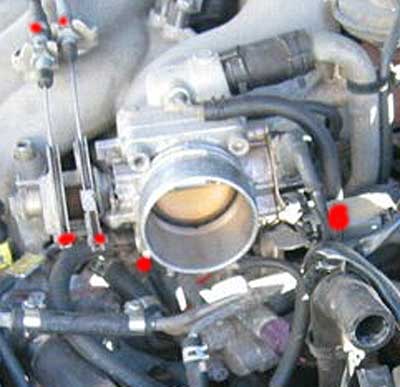
-Remove a short vacuum hose on the bottom of the TB that
connects to the intake plenum
-Remove the 4 hex bolts using a criss-cross pattern and remove
the TB
-For added stretch you might have to unclip the TPS
harness from its mount
Intake Plenum
-Unplug and remove the three rear coil packs
-Remove three ground straps (10mm bolts) 2 on front of
plenum, one on left side *Take a dremel or steel wool or something and clean
these ground straps and mounts to get the oxidation off, these need to make
good grounds!*
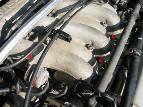
-Remove the vacuum hose from the power valve on the left
side of the plenum (N/A for auto)
-Remove the tiny cruise control vacuum hose from the rear
of the plenum
-Remove the mid-size vacuum hose on the rear of the plenum
that routes to the brake booster
-Remove the mid-size vacuum hose right underneath that
(this one meets a metal pipe which eventually winds up at the PCV valve.
-Now, remove the two 12mm bolts that this PCV metal pipe
connects to the plenum with
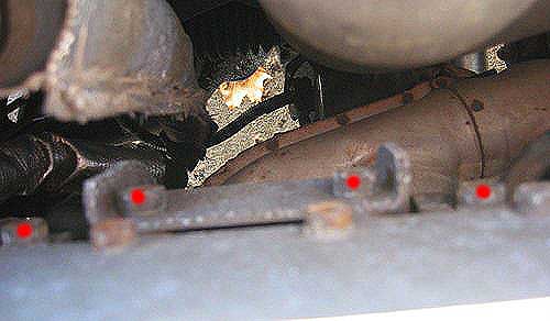
-While you’re down there, remove the two 12mm top bolts of
each plenum stiffening plate (only one plate is shown in the picture, there
is another to the right by the EGR)
-Take your big adjustable wrench and crack the big nut
loose on the EGR valve. Loosen it all the way until it moves freely and you
can see a gap between the EGR valve and metal EGR tube
-Remove the 4 remaining vacuum lines by the throttle body
location.
-This one’s hard to see, but there are 4 12mm bolts
holding on the EGRC valve on the lower right side of the plenum. Two on the
right side, two on the back side (one is not visible in the pic)
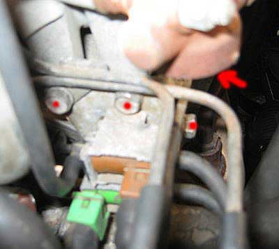
-Remove the 10mm bolt holding on a metal vacuum line mount
on the right side of the plenum, in front of the throttle body. It has a
yellow sticker on the mount.
-Now all you have to do is crack loose the 6 hex nuts in a
criss-cross pattern and pull off the plenum! If it doesn’t come off freely,
hit the “Nissan” part lightly with the palm of your hand. Now, when removing
the plenum, make sure everything is disconnected before you rip something off
Fuel Rails
-Loosen the screw clamps for each of the 4 small fuel
lines (2 on each rail)
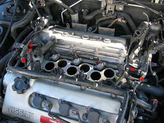
-Remove the fuel “T” line on the left side by removing the
two 10mm bolts. Be careful not to drop these down the intake manifold as
you’ll have to fish it out of the intake port of the head if you do (speaking
from experience here)
-Break loose the fuel lines and be prepared for some fuel to
spill out. Have rags handy. Remove the fuel “T”
-Now remove the 4 hex bolts of the fuel rails. Be prepared
to gather a plastic spacer and metal washer for each bolt as they will fall
and get lost easily. Remember how they fit! Plastic washer on bottom, then
fuel rail, then metal washer on top, then bolt.
-Lightly pull up on the rails, when they are loose you can
remove the right fuel lines. Do not drop the fuel rails, injectors are
fragile and expensive!
-Watch for any loose fuel injector grommets (where the
fuel injectors sit in on the manifold). Don’t lose these unless you have new
ones ready to go.
Intake Manifold
-Remove the left radiator hose and the smaller bypass hose
right next to it. You only have to disconnect them from where they meet the
manifold
-On the right side, remove the three bolts that hold on
the coolant tubes to the right side of the manifold. You may have to pry a
bit to get this off as it’s sealed on with liquid gasket.
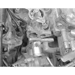
-Disconnect the coolant temp sensors (big one and small
one, be careful as these electrical connectors are brittle, and you’ll have
to pry the small metal wire clip to remove it)
-Now crack loose the 4 nuts (not bolts yet!) in a
criss-cross pattern, 2 on each side of the manifold
-Now loosen the 6 hex bolts, again in a criss-cross
pattern (important, you don’t want to warp the manifold by improper untorquing)
-Make sure you gather the washers that go with the nuts
-Pop off the manifold (you might have to pry a bit)
Water Pipe
By now, you can see the knock sensor and the pile of crud
in the valley of your engine, but there’s no way to break the sensor bolt
loose because the water pipe is in the way!
-Remove the two nuts and washers on the left side
(connecting to the water pump)
-Remove the two bolts that bolt vertically down
into the engine block on the right side.
-Now, using a LARGE flathead screwdriver, pry the water
pipe off the studs on the water pump side and you’ll be able to hold the
water pipe up to get to the knock sensor. Much easier than removing the
thermostat housing and all those coolant lines on the right side
Knock Sensor
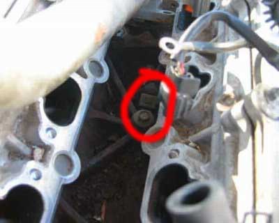
Finally, one bolt and it’s off. Clean the contact point
thoroughly since any dirt or gunk will make the sensor less effective. Now,
put the new sensor in and BE CAREFUL with it. Remember not to drop it or hit
it against anything. Even when bolting it down take extreme care, you do NOT
want to over tighten it! I couldn’t find a torque figure in the FSM so I just
tightened it down until I felt resistance and went about another half turn.
My uncalibrated torque right arm says it was about 15-20 lb/ft.
Now it’s time to clan the gasket surfaces on the head, manifold,
plenum and throttle body. Use a paint scraper for the best results. A bit a
steel wool won’t hurt either. Make sure no debris or anything falls into the
intake ports in the head. Also clean off the water pipe where it was sealed
with liquid gasket
Installation is in the reverse order of removal. Use a
solid bead of liquid gasket on all surfaces. Completely circle around all
pipes (on the right side of the intake manifold, the coolant pipes that
attach have two pipes. Make a circle around each hole so they don’t leak into
each other). Don’t use TOO much liquid gasket though. A thin solid bead is
all that is needed. Allow at least an hour for it to dry (by the time you get
everything else back together, at least an hour will have passed)
Intake manifold torque for the hex bolts is 20 ft/pounds.
For the 4 nuts it is 24 ft/pounds.
Again, torque them in a criss-cross pattern (middle bottom
left, middle top right, middle bottom right, middle top left, far bottom
left, etc)
Fuel rail bolt torque is 20 ft/lbs
Intake manifold hex bolt torque is 20 ft/lbs. Criss-cross
pattern.
Throttle body torque is 15 ft/lbs, criss-cross pattern
Make sure you replace all the plastic spacers and washers
correctly when you replace the fuel rails.
When replacing your coolant, fill it up to the top of the
radiator cap. Now, carefully open the 10mm nut by the large coolant bypass
hose on the right side of the intake manifold (by the two pipes and the
coolant temp sensors). This is a purge valve and releases the air in the system
as you fill it up.
Start it up and check for leaks. When all done, take it
for an easy test drive quick around the block then check for leaks when you
return. On the first real drive, drive slowly as if you were breaking the car
in. The metal manifold gaskets need a complete heat cycle to seal correctly.
You don’t want to risk doing this over again! Then disconnect the battery
(negative first, then positive) and let it sit overnight. In the morning,
enjoy your newfound VE power!
|